Part Loading & Fixtures
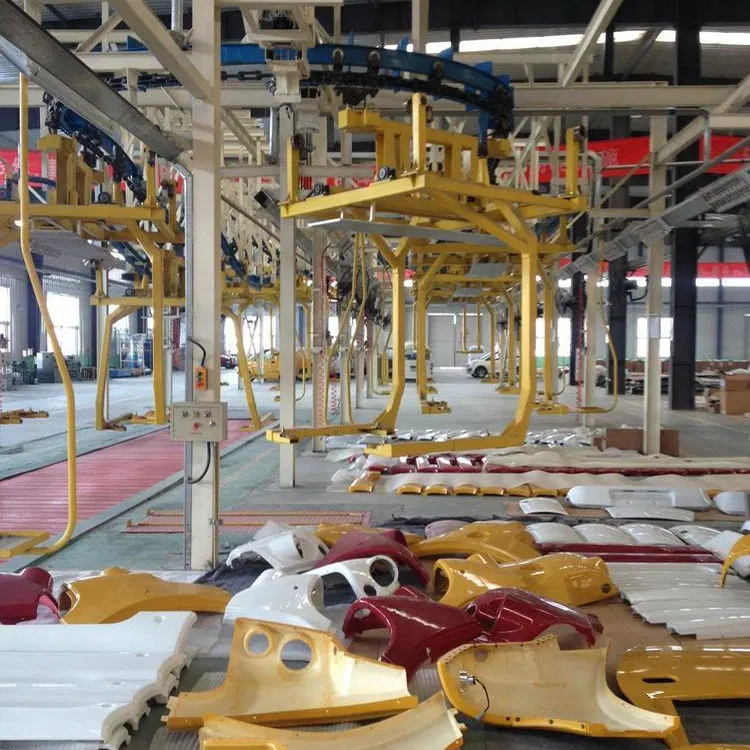
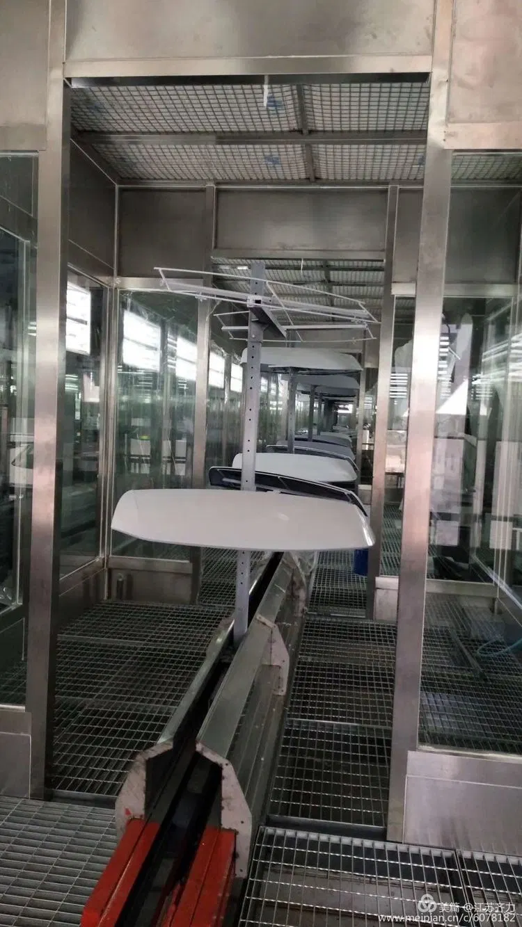
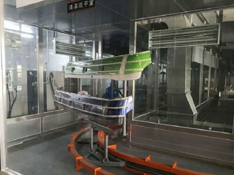
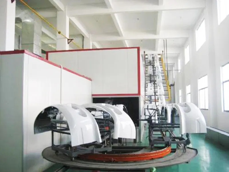
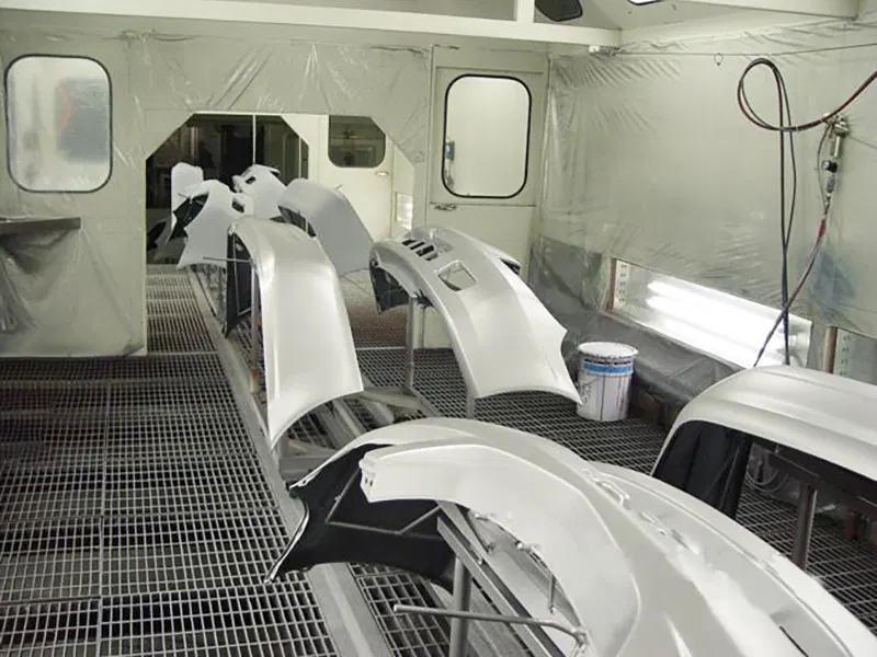
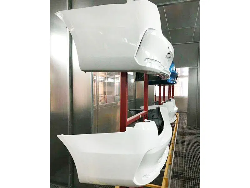
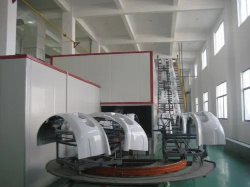
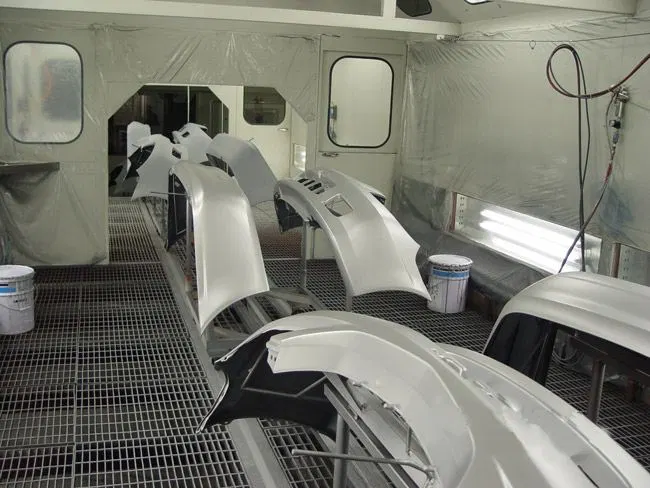
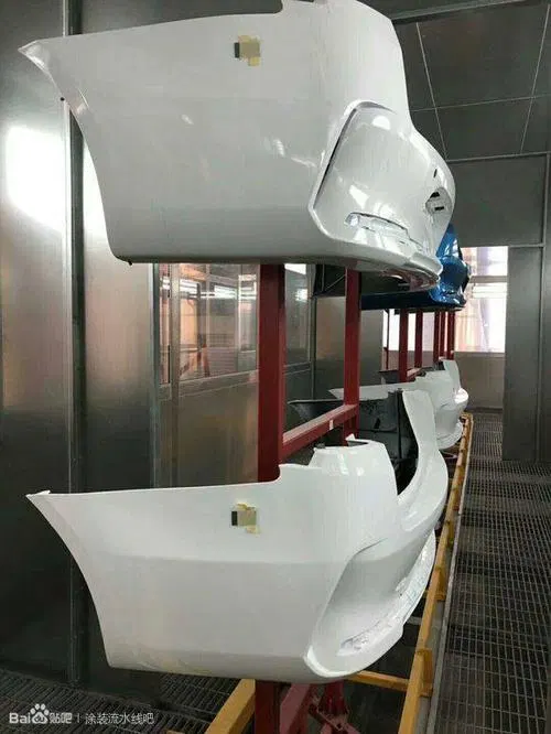
Fixtures and loading methods developed around bumpers, bus parts and automotive subassemblies.
Purpose-built coating systems for bumpers, bus components and other automotive parts.
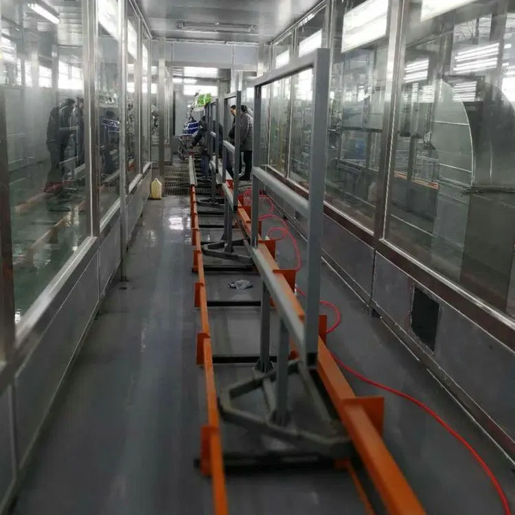
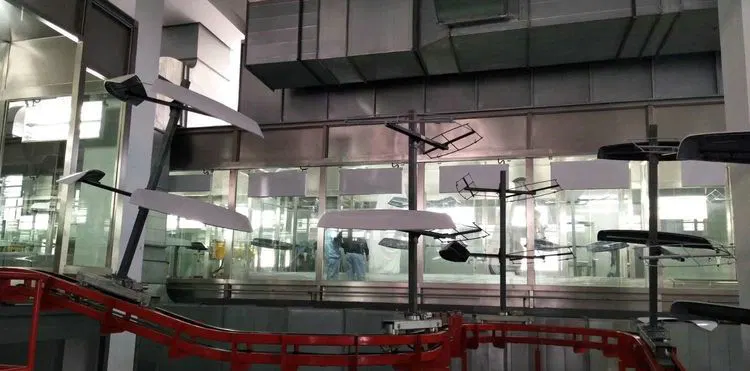
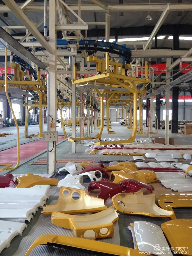
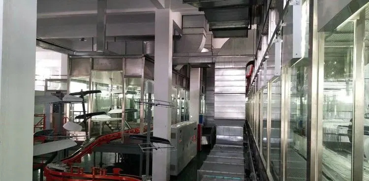
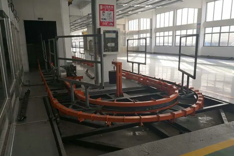
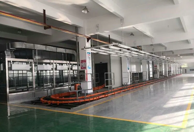
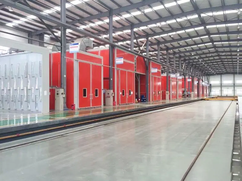
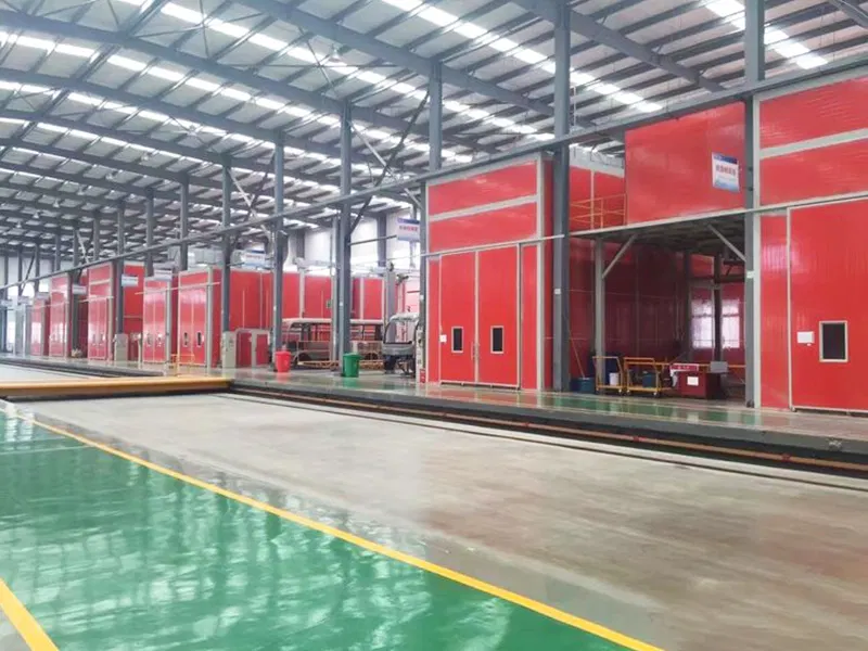
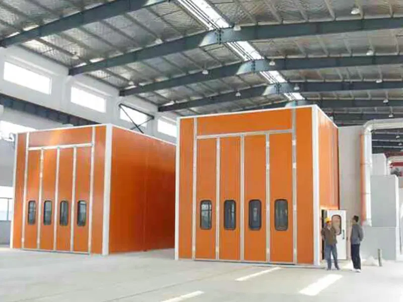
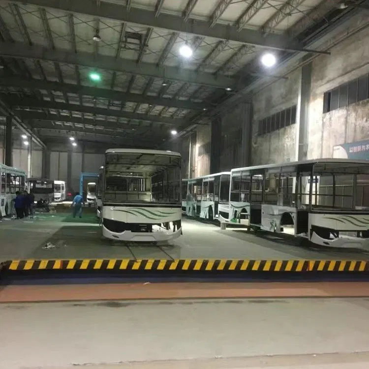
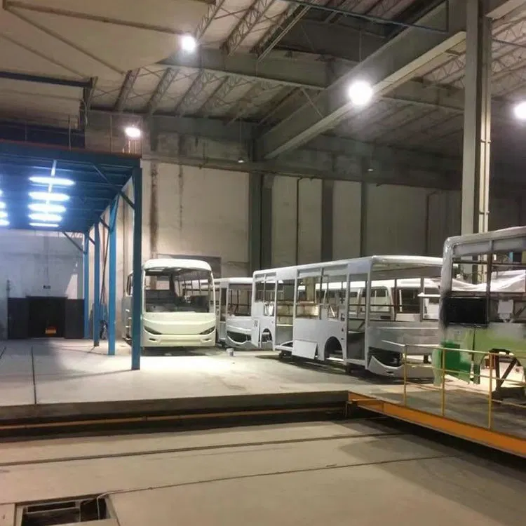
The catalog identifies automotive applications and illustrates bus-related coating, material handling and integrated assembly environments. Automotive part fixtures, cycle time and coating steps require project-specific design.
The catalog shows application areas; it does not provide a complete specification for every automotive component type.
Source: JI HENG TECHNOLOGY product catalog, PDF pages 4, 8, 10, 13, 17.
View English product overview (PDF) →These are the engineering modules to review for this type of system. Final configuration follows the approved project scope.
Fixtures and loading methods developed around bumpers, bus parts and automotive subassemblies.
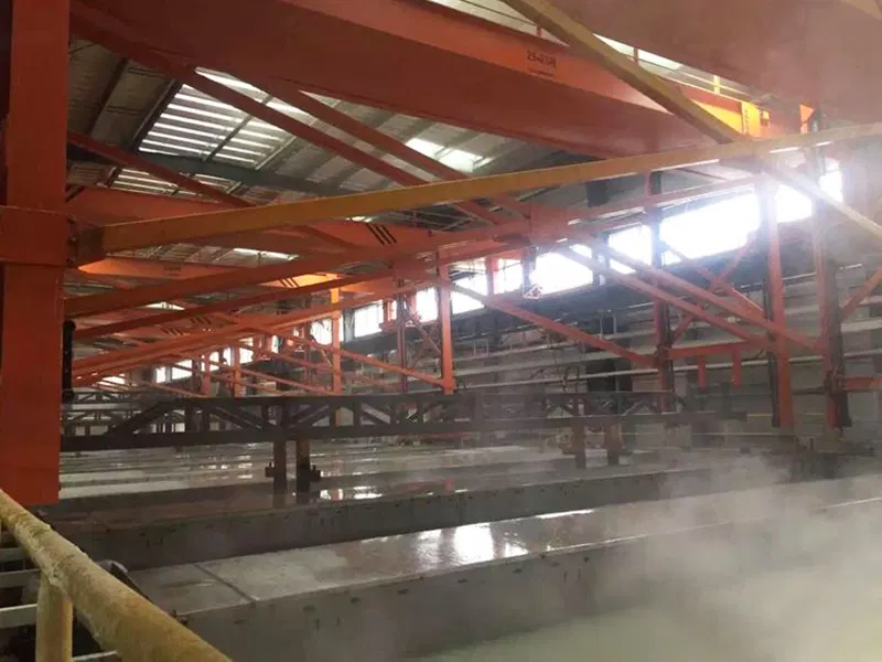
Cleaning and preparation stages configured for substrate and corrosion requirements.
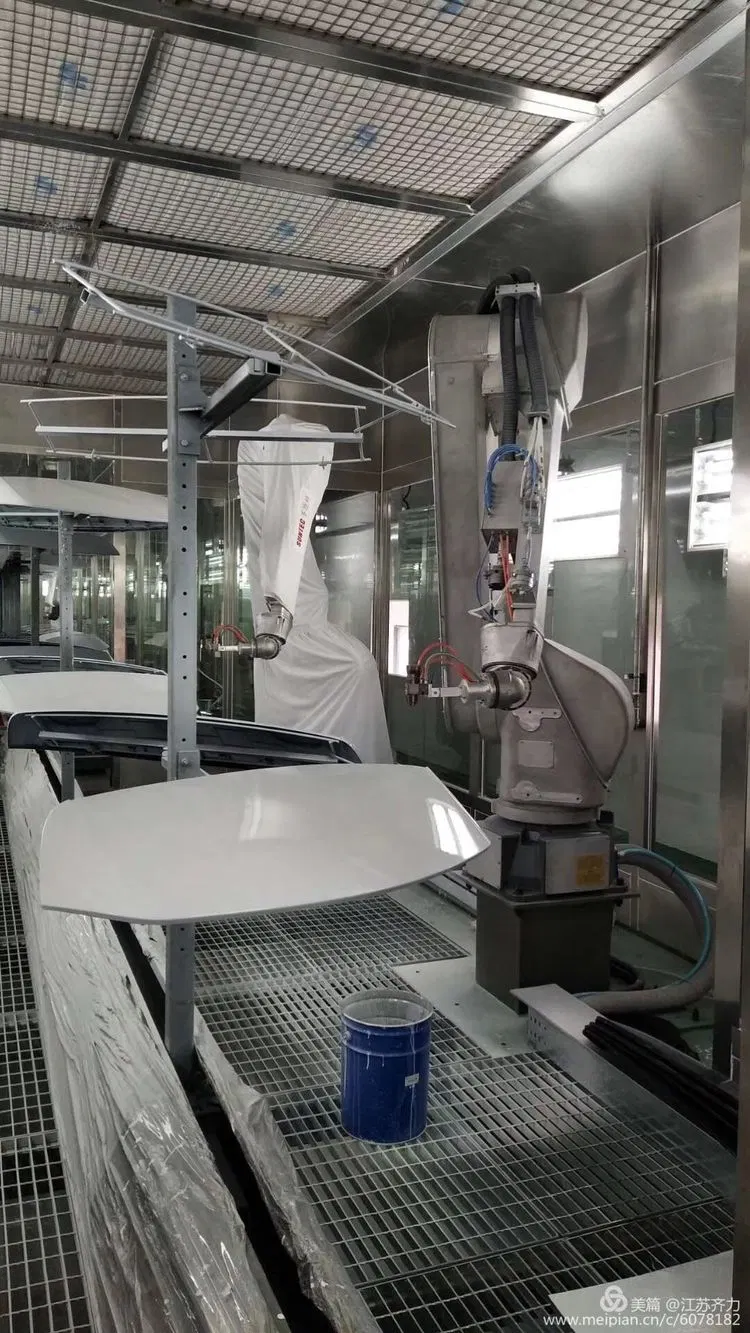
Robot or reciprocator-based application for repeatable coverage and finish control.
Process stages matched to the approved liquid or powder coating system.
Material flow, buffers and line interfaces aligned with the production takt.
Inspection, rain-test or downstream interfaces can be integrated where required.
These are design inputs, not a fixed model specification. No standard dimensions, capacities or performance figures are asserted without a confirmed project drawing and calculation.
| Maximum workpiece size | Designed to the approved workpiece envelope and handling method |
|---|---|
| Production capacity | Calculated from takt time, shifts, loading and process dwell time |
| Coating and curing process | Selected for the substrate, coating material and finish specification |
| Conveying method | Overhead, floor, accumulation, indexed or custom handling |
| Energy and controls | Agreed for available site utilities and the required control platform |
| Environmental system | Selected from coating material, exhaust condition and local requirements |
The customer and engineering team confirm the destination country, installation site, applicable laws and standards, technical parameters and acceptance criteria in the signed project documents. Custom design does not by itself establish certification or legal compliance.
Discuss the workpiece, substrate and finish with our team. These application areas are planning examples; the gallery photos may show other configurations.
Selected photos from the supplied product image library. These views may represent different projects and configurations.
These classified equipment photographs come from the supplied image library. Customer identity, installation date and process settings are not yet verified as case-study data.
Request a project-specific layout and engineering scope for internal evaluation.
Send us your workpiece or process details, production target and factory layout for an application-specific proposal.